Project Introduction
A water pump is a machine used to transport or pressurize liquids. It is widely used in daily life, commonly applied in urban water supply, sewage systems, agricultural irrigation, power plants, chemical industries, and many other fields. Currently, most water-pump management still relies on manual inspections, which are time-consuming and often cannot respond in time. Once a fault occurs, the issue cannot be resolved immediately, and normal water supply cannot be restored promptly.
With the development of the IoT industry, pump control is no longer limited to on-site manual operation. Remote pump control uses sensors to detect real-time water levels and automatically control pump startup and shutdown. If the master and slave stations fail to detect each other’s heartbeat signal during operation, the ongoing start command will be aborted, and an alarm will be triggered. The V-BOX device transmits data through the 4G network, enabling real-time reporting of alarm information.

Process Requirements
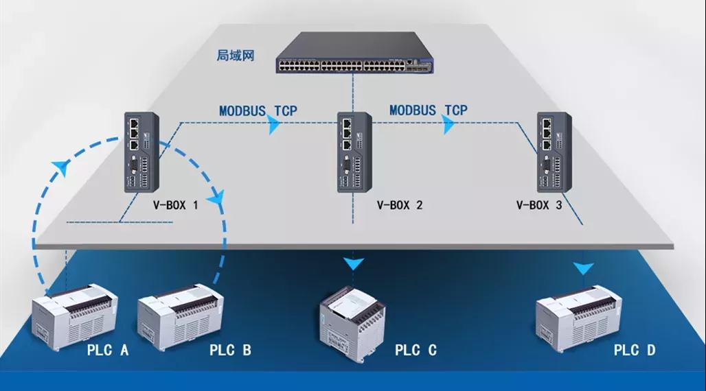
Two sets of control systems are used. Each system consists of one master station and four slave stations, which centrally collect the pool’s liquid-level data and remotely control pump startup/shutdown at each slave station to achieve centralized management.
Although the overall process is straightforward, multiple external factors must be considered. During programming, various potential abnormal conditions must be taken into account, and early-warning messages should be displayed on the interface. For example:
● If there is an issue with the centralized liquid-level data, the system must determine whether the sensor is disconnected.
● If device data transmission is interrupted, it must determine whether the V-BOX at the centralized station is offline or the PLC has stopped running.
● If the device data cannot be updated, it must determine whether the V-BOX at the control station is offline or the PLC has stopped running.
Case Analysis
The solution exchanges data among four PLCs through V-BOX devices. The centralized control station uses the more powerful Smart V-BOX S-4G, while the control stations use the cost-effective E-4G. The PLC selected for the control system is LX3V-0806MR-A, with LX3V-2ADI-BD for analog data acquisition, and PI3102i as the HMI for interface display.
Program Introduction
1. Plan all data parameters required for interaction within the system.
2. Address mapping:
The data is mapped using double-word integers. For example, in the command data sent from the master to the slave,the low byte contains heartbeat data and real-time data, the high byte contains control words, including start, stop, and fault reset. The V-BOX address-mapping function ensures that frequently changing data can be written and transmitted effectively in real time, supporting bidirectional real-time reading and writing to guarantee mapping success.

3. Master PLC program segment:
If the master PLC does not receive heartbeat updates from a slave PLC for a preset time, it outputs an alarm.
4. Slave PLC program segment:
If the slave PLC does not receive heartbeat updates from the master PLC for a preset time, the slave PLC stops the equipment.
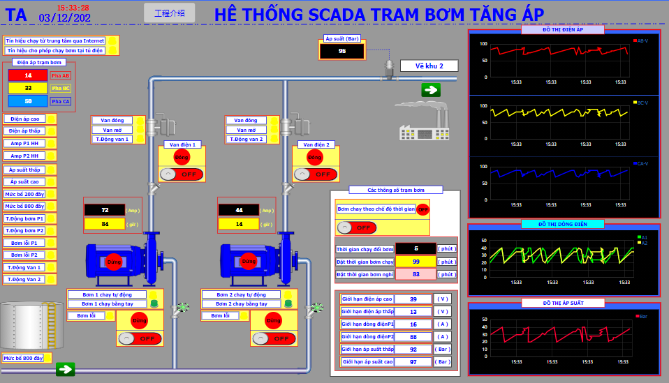
HMI Screen